

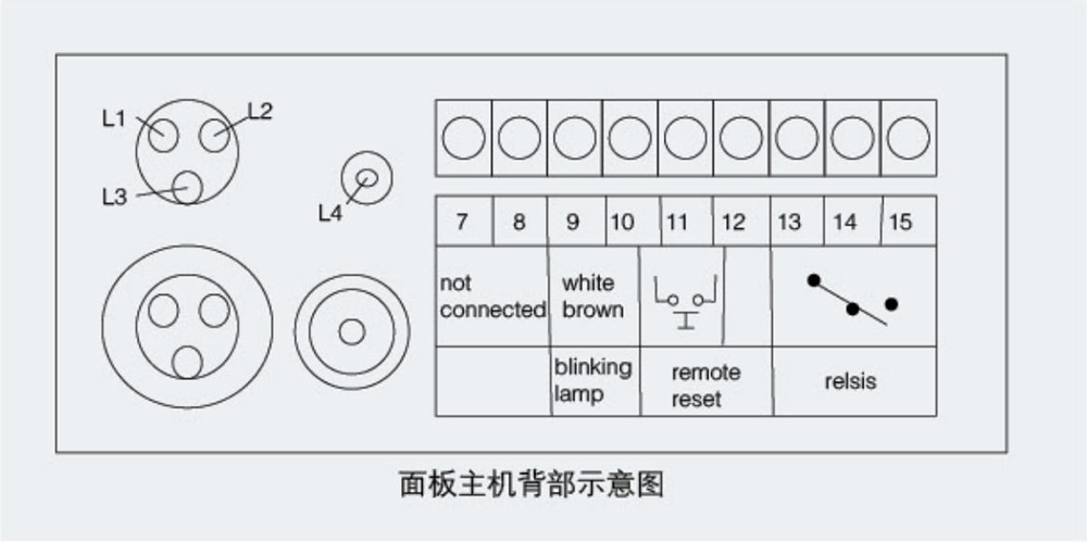
 panel type ground short circuit fault indicator")
With the widespread use of ring network switchgear and cable branch boxes in power grids, the issue of timely locating cable fault sections has become increasingly prominent. The EKL4 short-circuit and ground fault indicator provides the best solution to this problem. The EKL4 short-circuit and ground fault indicator is installed on ring network switchgear and cable branch boxes in 6kV-36kV distribution network systems to indicate time-related short-circuit and single-phase ground faults in corresponding cable sections. As shown in the schematic diagram below, when a short circuit or ground fault occurs in the ring network system, all fault indicators between circuit breaker A and the fault point carry the fault current. After detecting the fault current, the main indicator light flashes and an alarm sounds. The indicators between the fault point and the normally open contact remain in a normal state (no flashing, no alarm) because no fault current carries the fault current. Line maintenance personnel can quickly and promptly determine the fault section based on whether the indicator lights are flashing.
◆Short circuit fault alarm indication: The short circuit fault sensor is installed on a single-phase cable and constantly monitors the current in the power supply line. When its value reaches or exceeds the short circuit current alarm setting value (which can be set at the factory according to user requirements), the short circuit fault sensor sends an alarm signal. This signal is sent to the indicator host through optical fiber, and the corresponding short circuit fault indicator light flashes, indicating an alarm.
◆Ground fault alarm indication: The ground fault sensor is installed on the unshielded part of the three-phase cable branch and detects the zero-sequence current value of the three-phase cable. When the value reaches or exceeds the ground current alarm setting value (this value can be set at the factory according to user requirements), the short circuit fault sensor sends an alarm signal and transmits this signal to the indicator host through optical fiber. The ground fault indicator light flashes and issues an alarm indication.
◆Low battery alarm indicator: When the internal battery voltage of the indicator drops to 2.7V, an alarm signal is generated to prompt maintenance personnel to replace the battery. This alarm signal can last for approximately two months. An external power supply interface is also available for use with an external power source.
◆Short-circuit operating current: 400~1500A selectable (accuracy ±10%), delay 20~300ms, which can be determined by the user when ordering (default factory setting is 800A, 20ms);
◆Grounding operating current: 5~50A selectable (accuracy +10%); delay 20~300ms selectable, to be determined by the user when ordering (default factory setting is 15A, 20ms);
◆Short-circuit sensor cable diameter: cable outer diameter ≤ 40mm (other specifications can be customized);
◆Grounding sensor cable diameter: cable outer diameter ≤ Ф120mm (other specifications can be customized);
◆Working environment: -40℃ to 75℃, relative humidity ≤95%RH; waterproof, acid-proof, and salt spray resistant;
◆The operating power supply is either lithium battery powered or AC (DC (5V~10V) + 15%)
◆Remote signal contact capacity: AC220V/1A
◆Remote signal contact reset methods: manual button reset/automatic reset
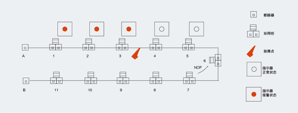
As shown in the diagram, the fault occurs between ring main units 3 and 4. Therefore, disconnecting the load switch of unit 3 and then closing circuit breaker A will restore power to ring main units 1, 2, and 3 and their branch systems. Power to units 4 and 5 will be restored by closing the normally open contact of unit 6. In this way, only a section of the faulty cable is isolated, ensuring that all loads can be restored to power in a timely manner.
Using fault indicators to locate faulty sections is far faster and more efficient than the traditional two-way method and the opening and closing test power supply method. Moreover, it does not have the risks associated with these traditional methods (such as potential injuries caused by insulation tests), making it a good way to improve power supply reliability.
◆Host
◆Automatic reset time: 1s-40h, continuously adjustable (factory set), accuracy ±1%;
◆Power supply: 3.6V high-efficiency lithium battery, the main unit has a battery replacement alarm function;
◆Operating current: < 5uA;
◆Alarm indicator operating current: <0.5mA;
◆Battery lifespan: ≥5 years;
◆Remote transmission manual output relay capacity: 230VAC/2A
◆Ambient temperature: -40℃ ~ 75℃
◆Ambient humidity: ≤95% (relative humidity), no condensation
◆ Maximum withstand current of short-circuit fault sensor: thermal stability 20kV/4s, dynamic stability 50kV/0.3s
◆Main unit dimensions: 96x48x80mm
◆Short circuit fault alarm current: ≥150A continuously adjustable (factory setting)
◆Accuracy: Error < ±10% across the entire temperature range
◆Delay: Adjustable from 20 to 300ms (factory set)
◆Ground fault alarm current: Used when the neutral point is not grounded or when the current is small.
◆Grounding system 10A-40A continuously adjustable (factory set)
◆Accuracy: Error < ±10% across the entire temperature range

ZW7-40.5户外高压真空断路器ZW7-40.5户外高压真空断路器ZW7-40.5户外高压真空断路器ZW7-40.5户外高压真空断路器

ZW8- 12户外高压真空断路器ZW8- 12户外高压真空断路器ZW8- 12户外高压真空断路器ZW8- 12户外高压真空断路器

ZW10-12户外交流高压真空断路器ZW10-12户外交流高压真空断路器ZW10-12户外交流高压真空断路器ZW10-12户外交流高压真空断路器

ZW20-12F户外柱上高压智能真空断路器ZW20-12F户外柱上高压智能真空断路器ZW20-12F户外柱上高压智能真空断路器ZW20-12F户外柱上高压智能真空断路器

ZW32-12户外高压真空断路器ZW32-12户外高压真空断路器ZW32-12户外高压真空断路器ZW32-12户外高压真空断路器

ZW32-12F户外交流高压真空分界断路器ZW32-12F户外交流高压真空分界断路器ZW32-12F户外交流高压真空分界断路器ZW32-12F户外交流高压真空分界断路器

WLS-10-1.1-1.4WLS-10-1.1-1.4WLS-10-1.1-1.4WLS-10-1.1-1.4

WLS-35户外三芯WLS-35户外三芯WLS-35户外三芯WLS-35户外三芯

WLS户外单芯WLS户外单芯WLS户外单芯WLS户外单芯

WLS户内外冷缩三芯WLS户内外冷缩三芯WLS户内外冷缩三芯WLS户内外冷缩三芯

NLS-35户内冷缩三芯NLS-35户内冷缩三芯NLS-35户内冷缩三芯NLS-35户内冷缩三芯

NLS-35户内单芯NLS-35户内单芯NLS-35户内单芯NLS-35户内单芯
Address:No.1, Lituo New Building, Keaisi Road, Xiangyang Industrial Zone, Liushi Town, Yueqing City, Zhejiang Province, China
Phone:+86 0577-62861931
Fax:0577-61778390

Follow official account