

 two-in-one overhead line fault indicator")
The JDX and 1DX have the same appearance, features, functions, applications, and technical specifications. However, their internal structures and working principles differ. The 1DX contains only one core chip that can only detect short circuits. The JDX, on the other hand, contains a combined intelligent detection chip that detects both short circuits and ground faults. However, the accuracy of the passive fault indicator in detecting ground faults is relatively low. When connected to an asymmetrical current source (signal source), the accuracy of ground fault detection can reach over 95%.
◆ Fault indication: During normal operation, the window displays in white; when a short circuit or ground fault occurs, the window displays in red.
◆Online operation: Installed directly on the line, maintenance-free.
◆Strong anti-interference: The signal is not affected by lines, inrush current, high-order harmonics, current fluctuations, cable distributed capacitance bypass.
◆Automatic Reset: After the operation is completed, the device will automatically reset after a set time.
◆Live loading and unloading: Live loading and unloading is very simple and does not affect the operation of the line.
The short-circuit fault principle in the combined grounding and short-circuit principle is the same as that in the 1DX.
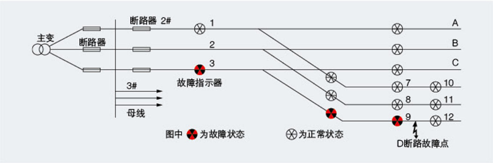
Grounding detection principle: The first half-wave of the capacitive current and the first half-wave of the voltage at the instant of grounding are sampled and compared in phase. If the sampled capacitive current changes abruptly and exceeds a certain value, and is in phase with the first half-wave of the voltage at the instant of grounding, while the conductor-to-ground voltage decreases, then a grounding fault is determined to have occurred on the line. The fault indication diagram used to determine grounding shows that indicators 3, 6, and 9 of phase C on line #2 turn red while indicator 12 remains white, indicating a fault at the output point.
◆ Installed in the middle section and at the branch entrance of long lines, it can indicate the faulty section and faulty branch of the line.
◆ Installed at the transformer outlet, it can determine whether the fault is caused by the user.
◆ Installed at the user's transformer inlet, it can determine whether the fault is caused by the user.
◆ Installed at the connection between the cable and the overhead line, it can distinguish whether the fault is in the cable section.
Figure A shows the installation tools for 1DX, JDX, and JDG. The specific installation method is simple: place an insulating rod at the bottom of the installation tool, unscrew the top bolt of the indicator, insert it into the installation tool, and then snap the indicator into the cable. Figure B shows the installation tools for JDX-Y.

ZW7-40.5户外高压真空断路器ZW7-40.5户外高压真空断路器ZW7-40.5户外高压真空断路器ZW7-40.5户外高压真空断路器

ZW8- 12户外高压真空断路器ZW8- 12户外高压真空断路器ZW8- 12户外高压真空断路器ZW8- 12户外高压真空断路器

ZW10-12户外交流高压真空断路器ZW10-12户外交流高压真空断路器ZW10-12户外交流高压真空断路器ZW10-12户外交流高压真空断路器

ZW20-12F户外柱上高压智能真空断路器ZW20-12F户外柱上高压智能真空断路器ZW20-12F户外柱上高压智能真空断路器ZW20-12F户外柱上高压智能真空断路器

ZW32-12户外高压真空断路器ZW32-12户外高压真空断路器ZW32-12户外高压真空断路器ZW32-12户外高压真空断路器

ZW32-12F户外交流高压真空分界断路器ZW32-12F户外交流高压真空分界断路器ZW32-12F户外交流高压真空分界断路器ZW32-12F户外交流高压真空分界断路器

WLS-10-1.1-1.4WLS-10-1.1-1.4WLS-10-1.1-1.4WLS-10-1.1-1.4

WLS-35户外三芯WLS-35户外三芯WLS-35户外三芯WLS-35户外三芯

WLS户外单芯WLS户外单芯WLS户外单芯WLS户外单芯

WLS户内外冷缩三芯WLS户内外冷缩三芯WLS户内外冷缩三芯WLS户内外冷缩三芯

NLS-35户内冷缩三芯NLS-35户内冷缩三芯NLS-35户内冷缩三芯NLS-35户内冷缩三芯

NLS-35户内单芯NLS-35户内单芯NLS-35户内单芯NLS-35户内单芯
Address:No.1, Lituo New Building, Keaisi Road, Xiangyang Industrial Zone, Liushi Town, Yueqing City, Zhejiang Province, China
Phone:+86 0577-62861931
Fax:0577-61778390

Follow official account