

 overhead transient characteristic local fault indicator")
Economic development and improved living standards have placed higher demands on power distribution network construction. Power distribution networks are complex and prone to faults. Determining the location of a fault by disconnecting sectionalizing switches and testing power supply poses a significant risk to the safety of lines and equipment operation. Utilizing highly integrated power distribution interruption mechanisms to achieve fault identification, fault isolation, network reconfiguration, reactive power and voltage control, and optimized operation of the power distribution network is crucial. However, installation and operation are complex and difficult to implement in some areas. Using simple, low-cost fault indicators for rapid fault location, or combining fault indicators with communication to remotely transmit fault information to form an online fault monitoring system, is of paramount importance for fault troubleshooting.
◆Working altitude: ≤3000m
◆Ambient temperature range: -30℃ to +75℃, maximum daily temperature difference: 25℃
◆Ambient humidity: ≤99% (relative humidity)
◆Sampling
◆ Current sampling range: 0-800A
◆ Current sampling accuracy: ±5%
◆ Seismic resistance: Earthquake intensity 8 degrees, ground horizontal acceleration 0.3g, ground vertical acceleration 0.15g, simultaneous action for three sinusoidal waves, safety factor 1.67.
◆Long-term withstand current: 630A
◆Short-time withstand current: 31.5KA/4S
◆Action response time: 0.03≤t≤3s
◆Applicable voltage level: U≥6kV
◆Number of repetitions: ≥5000
◆Applicable conductor current: ≥10A
◆Static power consumption: ≤10Uw
◆Applicable wire diameter: 5≤d≤45mm
◆Display method: Simultaneous display of flip-up sign and light emission, within a 360° range of 500 meters.
◆Suppress inrush current: Eliminate malfunctions caused by inrush current during closing excitation.
◆ Fault reset time: Default 24 hours. During permanent fault power outages, it remains active and will reset within 5 minutes after power is restored.
◆Suggested installation location for the indicator
◆ Installed in the middle section of a long line, it can help determine the faulty section of the long line;
◆ Installed at the branch entrance, it can determine whether a line fault is in the main line or a branch line;
◆ Installed at the substation outlet, it can determine whether the fault is inside or outside the substation;
◆Installed at the connection point between the cable and the overhead line, it can distinguish whether the fault is in the cable section or on the entire overhead line;
◆ Installed in plains or open areas, it can greatly reduce the workload of personnel searching for cables;
◆ When installed in areas with buildings or dense trees, it can greatly reduce the impact of the environment on work.
◆ Fault detection and location principles
◆Short circuit detection principle and location
When a phase-to-phase short circuit occurs in a power distribution line, a large current flows through the circuit between the substation and the fault point. The relay protection device activates, and the line trips. Therefore, there are four conditions for determining a short circuit fault:
(1) The line is energized
(2) A sudden current change of 1t > 200A occurs in the line. 1t is the starting current for sudden changes, and adjustments can be made according to the actual line.
(3) Duration of high current: 0.02s ≤ T ≤ 3s; T is the time of sudden change in current.
(4) Power outage
If all four conditions are met simultaneously, a short circuit fault is detected and determined to be present in the line at that location.
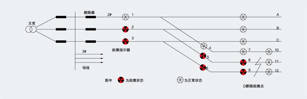
When a short-circuit fault occurs on the line, the short-circuit fault indicator senses the fault current, and the indicator's display window will change from white to red (or from non-illuminating to illuminating). This is based on phase indicators 2, 6, and 8 of line #2.
If the C-phase indicators 3, 6, and 9 on line 3 flip (or light up), while the indicators 11 and 12 do not flip (or light up), the fault can be quickly identified as point D.
For overhead lines, when a single-phase ground fault occurs, various complex transient phenomena will appear depending on the grounding conditions (e.g., metallic grounding, high-resistance grounding, etc.). These phenomena include the discharge current of the line-to-ground distributed capacitance and a drop in the voltage between the grounded line and ground. Based on these factors, the grounding criteria used in our product are as follows:
(1) The line is energized
(2) There is a sudden increase in transient capacitive current in the line: the transient capacitive current detected at the moment of grounding is greater than a certain value.
(3) The voltage of the grounding line drops by more than 3kV.
(4) Power supply to the line is uninterrupted.
When all four conditions are met, the detection terminal determines that a grounding fault has occurred at that location.
For cable lines, a zero-sequence current detection method is used. The starting value is set at the factory and applied to the incoming and outgoing cables. Once a ground fault occurs, the zero-sequence current value exceeds the set starting value to trigger the operation.
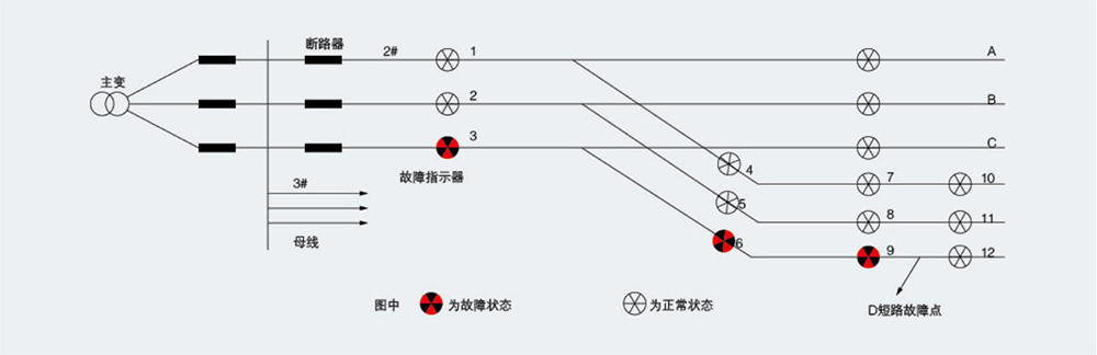
If the indicators for phase C (3, 6, and 9) of line #2 show up (or light up), while indicator #12 remains inactive (neither showing up nor lighting up), it can be determined that a ground fault has occurred at point D.
When the line experiences changes in its operating status, such as short circuit, grounding, power outage, or power restoration, the fault indicator detects the changing signal and determines whether a fault has occurred on the line. All indicators on the fault circuit from the fault point to the substation will activate and provide on-site indications.

ZW7-40.5户外高压真空断路器ZW7-40.5户外高压真空断路器ZW7-40.5户外高压真空断路器ZW7-40.5户外高压真空断路器

ZW8- 12户外高压真空断路器ZW8- 12户外高压真空断路器ZW8- 12户外高压真空断路器ZW8- 12户外高压真空断路器

ZW10-12户外交流高压真空断路器ZW10-12户外交流高压真空断路器ZW10-12户外交流高压真空断路器ZW10-12户外交流高压真空断路器

ZW20-12F户外柱上高压智能真空断路器ZW20-12F户外柱上高压智能真空断路器ZW20-12F户外柱上高压智能真空断路器ZW20-12F户外柱上高压智能真空断路器

ZW32-12户外高压真空断路器ZW32-12户外高压真空断路器ZW32-12户外高压真空断路器ZW32-12户外高压真空断路器

ZW32-12F户外交流高压真空分界断路器ZW32-12F户外交流高压真空分界断路器ZW32-12F户外交流高压真空分界断路器ZW32-12F户外交流高压真空分界断路器

WLS-10-1.1-1.4WLS-10-1.1-1.4WLS-10-1.1-1.4WLS-10-1.1-1.4

WLS-35户外三芯WLS-35户外三芯WLS-35户外三芯WLS-35户外三芯

WLS户外单芯WLS户外单芯WLS户外单芯WLS户外单芯

WLS户内外冷缩三芯WLS户内外冷缩三芯WLS户内外冷缩三芯WLS户内外冷缩三芯

NLS-35户内冷缩三芯NLS-35户内冷缩三芯NLS-35户内冷缩三芯NLS-35户内冷缩三芯

NLS-35户内单芯NLS-35户内单芯NLS-35户内单芯NLS-35户内单芯
Address:No.1, Lituo New Building, Keaisi Road, Xiangyang Industrial Zone, Liushi Town, Yueqing City, Zhejiang Province, China
Phone:+86 0577-62861931
Fax:0577-61778390

Follow official account